Thursday, April 22, 2010

Leon Dionne's Taig Lathe

Leon Dionne sent in some great details of his Taig Lathe setup.

My lathe is powered by a 1/4HP 220 volt 3 phase motor with a jack shaft attached to the motor

The motor is controlled by a VFD (variable frequency drive), which gives me speed control from zero to max, forward and reverse, controlled start and stop, and a number of other features which I have as yet not found a use for.

Why the need for a jack shaft?? At very low RPM, the motor also produces very low torque. With the reduction in speed, and conversely the increase in torque I get with the jack shaft,(a factor of approx 2.5), I can get a spindle speed of approximately 50 RPM and still get plenty of torque (the belts will slip before the motor will stall)

This method of mounting the dial indicator allows the use of the carriage stop.

The tailstock has the usual modifications, the lever extension is simply a 5 inch piece of 1/2 inch copper pipe with a brass knob locktited at the tip. A tommy bar replaces the hex screw.

Simple tip: Sliding a 7/8 inch ID O-ring over the carriage hand wheel, provides the friction required to prevent the hand wheel from "creeping" out of adjustment.

My motor mount is made of 2 inch angle iron and 1/4 inch slide rods mounted on a wood base.

A front view shows the belt tensioning screw.

Wednesday, April 21, 2010

Gerald Hynes Taig Accessories on his Mini Mill

Gerald Hynes sent in pictures showing his use of Taig accessories on his import mini mill.

Thought you might be interested to see a couple of fixture plates I made for use on my "non TAIG" milling machines but set-up for mounting many stock TAIG accessories for a variety of clamping options. the fixture plates are drilled and tapped 1/4"-20 on a 1" grid pattern. they mount to the mill with T nuts thru the counterbored holes using 1/4"-20 sockethead bolts. All unused holes in the grids are plugged with short set screws to keeps the chips out of the holes.


The TAIG vise sub-plate is drilled/tapped 10-32 on a 1" grid to allow use of the TAIG vise without modifing the existing counterbored mounting holes. Also since the TAIG vise jaws are mounted on the same spacing they could be removed for direct mounting to the plate. Also the 2 vises can be mounted end to end and with some reconfigration of the jaws allow clamping upto about 5 3/4"! Not bad for a pair of vises under $30 ea ! The beauty of the whole set-up is the ability to move work from the lathe to the mill and back without disturbing the part! Bear in mind that these are not precision plates and are merely made from affordable 6061 bar stock. If needed I can mount a sub-plate and then machine it flat at that position and then mount work to it. Overall though they are very useful devices for most required set-ups. I have sanded them flat on a granite surface plate so the are generally good for the sorts of projects I undertake. I may at some point have a friend flycut them on his bridgeport for a more precise flatness and parallellism. Or at some point I may get my own bridgeport sized CNC knee mill finished and flycut themself! The mill of course is a whole other project!

Tuesday, April 20, 2010

Bob Eckstein's Motorized Taig Lathe Power Feed

Bob sent in his latest project, a motor drive for the Taig lathe power feed.

A few shots of the drive I made for the carriage on the lathe.

The original drive.

I made a little hand-held control box with instant forward / reverse switches.

The motor is used in a majority of HP DESKJET printers. They can be had in thrift stores for usually under $5.00. The whole project cost maybe $15.00.

The motor mount is an "L" of 3/32 brass silver soldered to a hinge.

The friction drive to the gearbox input pulley is via a couple O-rings on the plastic pulley of the motor shaft.

Saturday, April 3, 2010

Carriage Depth Stop With Riser Blocks

A customer was wondering about the use of the carriage depth stop with the riser blocks installed.

Normal use of the depth stop.

Riser block installed. Note that the dovetail is offset to the rear.

The thumbscrew fouls against the riser, and the rod wouldn't hit the carriage.

Drilling a #21 hole.

Tapping #10-32

Works just fine. So a couple of minutes of non-precision work and the depth stop is now useable.

Thursday, April 1, 2010

X Axis Travel Stops for the Taig Milling Machine

Lately I've been needing some travel stops for the X axis (the table) of my Taig Mill. I finally broke down and just hacked out a pair. I didn't any design work and just made them up as I went along.

The project started by finally figuring out that the front t-slot of my Taig Mill table would accept #4 nuts. I started with a piece of 1/2" square free machining steel. I faced the top first. Then I picked up the edge.

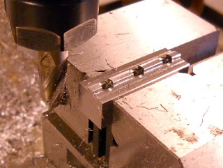
I started milling a tongue that would fit in the front t-slot of the table to keep the stop horizontal.

Finished tongue. The slot is about .125" wide so I made the tongue about .110The slot fills up with oil, chips, etc so a looser fit seemed like a good idea.

I used an end mill to get below the level of the surface as the drill for a #4 screw is just about the width of the tongue. I then center drilled and drilled through with a clearance drill for a #4-40 screw. The holes are about 1/4" from the ends and 1/2" apart.

I flipped the piece and counterbored for the screw heads with a 3/16" end mill. I'd probably go 1/4" if I made them again as the screw heads were a tight fit.

I sawed the piece in half. I could have just made two pieces to begin with but I really was doing this all off the top of my head.

I faced both ends flat of each stop.

I had to cut the screws to the right length (I use an electricians crimper that has screw shearing holes built in). The parts were deburred.

As you can see the #4 hex nut is a sliding fit in the t-slot. I'm a bit worried it will catch but so far it works fine. Maybe in the future I'll make a flat nut the full length of the stop.

The finished stop. While two screws probably would hold fine, 3 seems better. It's a bit of a pain to loosen three screws per stop but I definitely don't want it to shift and I don't want to have to over tighten the screws either.Seems rock solid and repeatable (there's a degree of feel) to a few thou. Chips caught between the stop and the post will likely be an issue though.
Also posted as an article at Cartertools.com